Main technical issue
For large prismatic parts to be machined, the setup time is of the same order of magnitude than the machining process time itself, ranging from half an hour to several hours of alignment time. Besides, if this setup process has not been performed correctly, shortage of material or excessive material for machining can occur. For workpiece setup, first, a rough part is marked out according to machining allowances (excess of material to be cut). “Marking out” is the process of transferring a design or pattern to a work piece, as the first step in the manufacturing process. The rough part is positioned on a surface table and, by means of scribers, blocks, indicators, punches or compasses, some datums or references (fiducials) are marked in the rough part. Once datums are defined in the marking out process, the part is aligned according to the machine axes. Zero-point clamping systems are not used for large prismatic parts (only for very small batches or loose units), therefore the workpiece manual alignment in-machine is necessary for each unit. Using dial indicators or machine touch probes, the rough part is measured with reference to the machine axes (using the previously defined datums) and the part misalignment is obtained. This part misalignment error value is used to align the part and this process (measurement + alignment) is repeated until the alignment of the part’s fiducials or marks is achieved in respect to machine axes.
Proposed technical solution
Alternatively to the marking-out process, photogrammetric measurement has been validated in by the INTEFIX project. A 3D metrology system based on photogrammetry technology has been developed. Algorithms and software has been developed to create a 3D point cloud of the workpiece geometry using photogrammetric markers. Software for best alignment of parts has been developed to obtain optimal alignment between the piece geometry (obtained by photogrammetry) and the CAM data ensuring there is no shortage of material or excessive material for machining. For the cases when on-machine measurement has to be carried out, an on-board camera system has been developed. The camera is clamped like a tool (using standards systems like ISO tappers or HSK), the imagining is captured by an external software synchronized with the machine, from different points and orientations thanks to the axis of the boring or milling machine. The information is sent by WIFI connection to the laptop where the photogrammetry software is running, and the results are analyzed by the operator. Alternatively to the manual alignment, a parallel kinematic architecture alignment table to support photogrammetric results has been designed and constructed. The alignment table has 3 Degrees of Freedom and it is used for the alignment of the workpiece in relation to the three rotation axes. The movable part of the table pivots around a spherical bearing and three hydraulic actuators controlled by LVDT sensors creates the linear movements for rotation around that spherical bearing. After alignment, the whole system is automatically stiffened, ready for machining using several work support elements and actuators. The complete system has been tested, including the automatic location of the part for avoiding material shortages at machining. This system has been validated by Goimek with different real workpieces.
Main advantages of the solution
This system has three main features that makes it suitable for large parts in a manufacturing workshop:
• Agility in the measurement (quick response);
• High precision in the captures thanks to the self-calibration procedure;
• The easiness to use with incremental adjustment method, making it usable by any kind of operators, without experience in photogrammetry.
This technology is less time consuming and can provide the best fit between the finished and rough parts’ volumes.


Part to be machined with photogrammetric markers (on-machine)

Software for measuring of photogrammetric markers

Software for best alignment of the workpiece
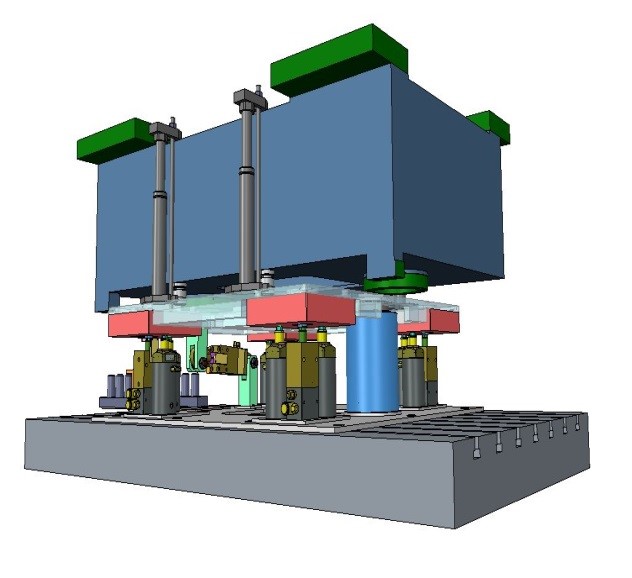
Alignment table, 3D model including part for test
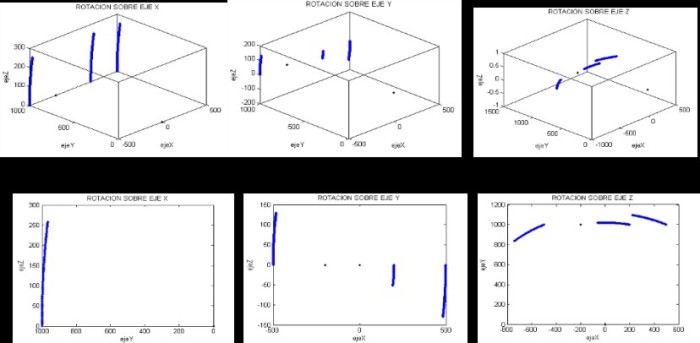
Simulation of actuators in parallel kinematic architecture
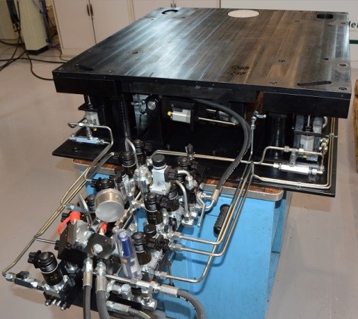
Alignment table, final assembly
Project:

Enterprises:
Sector
Machinery & equipment
Keywords
Intelligent fixtures, Modelling & Simulation